1971 Chevelle
November 5, 2002:
I decided to move the
November 13, 2002:
I ordered a
body rotisserie today, from Accessible Systems, Inc. in
November 19, 2002:
Major parts
orders placed yesterday from Moser Engineering (12-bolt rear w/3.08 gears &
Eaton Posi), Global West (Tubular Upper & Lower
A-Arms), BAER (complete 13” disc brake system w/B-body spindles), TireRack (BFG G-Force T/A KD tires) and Jeg’s
(wheels, locking lug nut kit, QA-1 coil-over shock conversion kit, QA-1 rear
shocks, Hotchkis boxed lower rear control arms & support braces). I already have boxed, adjustable Hotchkis
upper rear control arms left over from my ’72 SS restoration, new-in-box. Rear springs will be ordered at a later
date. I need to assess ride height
before buying the rear springs.
November 26, 2002:
Parts have
been coming like it’s Christmas! A portion of the Global West order has
arrived (upper A-Arms), the Moser 12-bolt housing & axles, Hotchkis stuff,
QA-1 conversion kit, Torqy II’s
& two of the four BFG tires are all here.
I couldn’t wait to see the wheel/tire combo, so one of the rear BFG’s was mounted onto the
17x9.5 Torq-Thrust II wheels today. WOW…..that is one cool looking, WIDE
tire! I have located several powder
coating companies around
November 29, 2002:
Today I
assembled the body rotisserie from Accessible
Systems, Inc. out of
December 14, 2002:
My younger
brother Scott, along with my friend Richard, started in Saturday morning to
separate the body from the chassis.
Things went along quite nicely and in no time, the chassis was rolled
outside, leaving the body hanging from the four arms of the shop lift. I spent the next couple of hours designing a
temporary set of caster wheels so the body could be stored off site. Unfortunately, the design was too flimsy and the
structure collapsed as we started rolling the body across the floor. We bolted the body onto my new rotisserie
instead. This car’s underbody is in
great shape, much better than my ’72 SS which had major rot requiring full
floor pan replacement panels, as well as a full trunk restoration. From what I could see, this car only needs a
small repair in the floorboard where the drivers feet
go, rear wheelhouse/trunk floor repair, and a few pinholes under the rear
seat. The sheet metal around the bottom
of the rear window opening is rotted, requiring some fabrication or splicing in
of a donor section. I still have not
assessed the condition of the rear quarter panels. The car body will have to stay here at the
shop for the time being. I’m going to
try stripping the chassis down to the frame by the end of the month so it can
be delivered to the powder coater in
December 21, 2002:
Starting
Friday night after work, I put the rolling chassis onto the shop lift and began
removing the following items: fuel &
brake lines, cross member, center link, tie rods, idler arm, steering box,
front wheels, spindle/brake assemblies, springs & upper a-arms. On Saturday, I finished the removal of the
lower a-arms, rear axle, rear suspension, and engine mount stands. By noon on Saturday, the frame was complete
stripped and moved up to my parents’ garage for a few body mount repairs. It will be delivered to the powder coating
company in
December 27, 2002:
I played
“hooky” from work today in order to perform two frame rust repairs on the
Chevelle. The two forward body mount
holes are susceptible to rusting and my frame was no exception. The holes were still intact,
however they were much larger than the correct size hole due to 31 years of
age. I sanded away all the rust on the top
of the frame around the holes using a 3M mini sanding disc and my right angle
die grinder. I then fabricated 3/16”
steel plates that fit the contour of the frame and welded them on with my mig welder. Using a
GM maintenance manual from 1971, I verified the distances between body mounting
holes and marked, punched, and drilled a new correct size hole in each
plate. The frame is now ready to head to
the powder coater (perhaps this Friday) in
January 2, 2003:
Happy New
Year everyone! The frame is strapped
down to my snowmobile trailer and I’m scheduled to push off at 6AM tomorrow
morning for Berkshire Custom Coatings.
Hope the snowstorm shows up later in the day, after I’m already back home!
January 3, 2002:
It’s
there! Should be finished
in two weeks.
January 20, 2003:
The frame was
finished on time and picked up today. I
was awestruck at the beautiful job done by Berkshire
Custom Coating, Inc. in
January 26, 2003:
Today I began
putting the first of several coats of POR-15 and Chassis Coat black paint on my
new Moser 12-Bolt Posi rear axle. Moser ships their axles bare, so I thought
POR-15 would be a great alternative to powder coating the housing. Powder coating the housing would have meant I
needed to gut the housing, and I didn’t want to un-do all of Moser’s set
up. After the housing is finished &
dry, I can begin assembling the rear axle & suspension onto my frame. Unfortunately, I’m still waiting for my lower
tubular A-arms from Global West. I have
called repeatedly, and gotten a song & dance each time.
February 9, 2003:
Today I
installed all four of the front A-Arms.
The tubular Global West pieces slid right into place with no trouble at
all. GW installed
February 15, 2003:
This morning
I installed the following front suspension parts: QA-1 shocks, QA-1 coil over springs, BAER
“loaded” spindle with Eradi-Speed brake system. In total, I probably spent around an hour and
fifteen minutes to install the parts on both sides! These parts are beyond beautiful….and
everything fits perfectly. After
installing, I attempted to bolt on my front wheels & tires, but encountered
difficulty installing my lug nuts. I
ordered 7/16-20 nuts, but they don’t want to thread onto to the studs. I even took the retainer nut (used for
shipping only, to keep the rotor tight) up to the hardware store but couldn’t
find any SAE or metric bolt, fine or coarse, that would fit it. I’m baffled!
A call to BAER on Monday is in order, to ask them what size studs these
are. Pictures are up on the site, under
Chassis, Suspension & Brakes section.
February 16, 2003:
I fought with
the installation of the massive HOTCHKIS front sway bar today. What should have taken only about 15 minutes
turned into a two hour odyssey! I even
managed to cross-thread the holes in the frame (my worst fear) but was able to
restore them with a tap. Finally, the
bracket bolts went in straight and the bar was mounted. End links went in like butter, and mate up to
the Global West lower a-arms beautifully.
Now it’s off to the TV to watch the Daytona 500.
February 17, 2003:
Today I put
the final coat of POR-15 chassis-coat on my Moser axle, then
installed my lower and upper rear Hotchkis control arms. Support braces were also installed. The support braces are now adjustable (very
trick) and will allow for minor lengthening or shortening to
accommodate different tolerances.
More pictures on the Chassis, Suspension & Brakes section.
February 20, 2003:
The Moser
12-bolt rear axle was installed today, with the Hotchkis adjustable upper and
fixed lower control arms. Hotchkis
support braces tying the upper and lower front mounting bolts together were
already installed. Hotchkis lowering
springs, new rubber isolators, and QA-1 shocks were also installed. So far, all these parts have been going
together flawlessly!
February 22, 2003:
This morning,
I tackled the install of the rear axle shafts, BAER Tracker rear disc brake system,
and the Hotchkis rear sway bar. Most
everything went together smoothly, however I have discovered that the QA-1
shocks have too long of a travel. When
they are fully extended, the rear coil springs are loose and in danger of
falling out. Shorter shocks should solve
the problem. I also encountered a
problem with the caliper mounting of the BEAR rear brakes. There appears to be insufficient clearance
between the caliper bracket and the rotor.
Instructions indicate a minimum of .030” and I have less than that. Some minor machining of the mounting surface
might solve the problem. Wheels went on
great, look awesome. LOTS OF PICTURES
POSTED TODAY UNDER THE “CHASSIS, SUSPENSION & BRAKES” SECTION OF MY
SITE. ENJOY!!!!
March 1 & 2, 2003:
With the black
hands to prove it, I applied POR-15 glossy paint to several small brackets,
front steering center link, inner tie-rods, idler arm, motor mount stands, and
steering box mounting bolt heads/washers.
After another coat, I will apply POR-15’s Chassis-Coat as a sealer. The new AGR 12:1 quick ratio box is ready to
install, along with the steering components including BAER anodized aluminum
adjustment sleeves & outer heim joint ends.
March 6-8, 2003:
Installation of the steering components, after being painted with
POR-15 & Chassis Coat black. Center
link, inner tie-rods, idler arm and BAER adjustment sleeves and outer heim joint rod ends.
AGR quick ratio steering box was also installed. On the 8th, I fabricated a rear
brake line bracket to attach the flexible rubber hose to the rear axle. Main brake line was also installed using
rubber coated adel clamps
along the frame. More work on the rear
brake lines is coming soon.
March 9, 2003:
The only
thing I did on the car today was install the rear brake line bracket I
fabricated. I took the stock mount off
the 10-bolt rear axle removed from the car, and welded on a mounting plate that
is held in position by the top two housing cover bolts. Pix under “Chassis,
Suspension & Brakes” section.
March 15 & 16, 2003:
The BAER
flexible stainless steel brake hoses were installed on both the rear axle and
the front brakes today. BAER supplies a
90-degree bracket to transition the hard line to the flex line on the rear
brakes. The bracket is held to the axle
tube using a large hose clamp. On the
front, the flex hoses attach to the caliper with a banjo style fitting, and the
other end attaches to the factory transition bracket bolted to the frame. Hard lines from there are routed in the
factory configuration to the proportion/distribution valve which is frame
mounted. I’ve purchased a used prop
valve, and after reconditioning it, will be bolted to the frame and the
front/rear brake lines will attach. All
brake lines are attached to the frame using rubber-coated adel clamps and self tapping screws. The one other thing I accomplished today was
moving my ZZ502 motor from storage into the shop. This engine was scored on Ebay, back in
January 2001. The seller stated that it
was in his Camaro, which he wrecked, and only saw around 3,000 miles of
use. Taking him at his word, I put it
into storage since returning from
March 22, 2003:
Today’s work
consisted of sandblasting & painting a used brake line proportioning
valve. I also applied a coat of paint
(POR-15 Gloss Black) to the master cylinder provided by BAER Performance
Brakes, to be used with the 4-wheel disc brake system installed on the car. While the first coat of paint was drying, I
did some exploratory work on my spare ZZ502, removing a cylinder head and
inspecting one bank of cylinders and pistons.
As stated above, this motor appears to be low mileage & clean.
March 29, 2003:
The spare
ZZ502 engine was partially disassembled again today to inspect the remaining
cylinders, pistons and head. All appear
well, so the motor was put back together and will be planted into the chassis
for mock-up purposes.
March 30, 2003:
Today I installed
a Lakewood Blow Proof Bell housing and mid-plate to
the ZZ502, added a set of polyurethane Energy Suspension engine mounts, and
lowered the mill onto my chassis. Not
wanting the motor to simply hang down towards the back, I fabricated a temporary
cross member to support the back of the bell housing till I purchase my
transmission, and figure out what I’m going to do about a cross member for the tranny. I might buy
a kit from Competition Engineering, and make the ends to bolt to the frame,
then have it powder coated. I might use
the stock unit as well, but mods to the transmission
mount are necessary. I robbed the
hi-torque mini starter from my LT-1 350/375 engine and bolted it to the
ZZ502. The dilemma I have now, is headers.
Full-length headers, like the Dynomax
ceramic-coated units I have in my ’72 SS, won’t interfere with the manual trans clutch Z-bar, but will be a problem with the
April 12, 2003:
My headers (Dynomax Ceramic-Coated) arrived this week, along with my
new brake line junction block. Today I
began the day by modifying the header flanges.
With the aluminum head bolts & washers, the headers will not fit
without grinding small notches in the bottom of the flanges. Not a big deal, as this is common for any BBC
head that doesn’t use stock size head bolts.
After headers were installed on the motor (I yanked out the motor to
install the headers & to test fit after notching) and the motor was
re-installed into the chassis. Plenty of
clearance at the brake line junction block and clutch z-bar.
April 19, 2003:
Today I
installed a rear axle breather line, using an Aeroquip 90-degree AN fitting and braided stainless steel line. The vent line terminates at a K&N
mini-filter up on the rear frame crossmember where it
won’t catch much road debris & dirt.
Then I modified the flange on my
April 26th, 2003:
Not so
fast! With the
May 2003:
My project
has come to a halt for the moment, due to several reasons, most of which are
related to time. There’s
only so many hours in a day, and two up-coming car shows are taking up my spare
time. I will be showing the ’72 Chevelle
SS in
August 2, 2003:
Well, if you read my header troubles from the April notes,
you will see that I thought using a set of Hedman
Elite ¾-length headers would solve my problems.
NOT! I got frustrated and ended
up damaging the Elites so badly I can’t use them. The fit was terrible, as they hit the frame crossmember under the oil pan. I decided to bolt on the Dynomax
headers again, and find a solution for the oil filter removal issues. With a plasma cutter, I removed a very small
portion of my lower control arm mounting pocket, allowing the filter to sneak
thru the headers and out towards the left front wheel. Issues with the headers are now over. The differences between this set of Dynomax pieces and the very same part # used on my ’72
Chevelle SS are paying off in only one area; the clearance at the brake line
distribution block is about ½ inch, more than enough to eliminate header heat
issues.
August
7, 2003:
The
August
12, 2003:
Thru the tracking function on RoadWay
Freight’s website, I discovered the
August
13, 2003:
In keeping with the theme of this restoration (Spend as
much money as possible, on any “trick” pieces possible) I decided to not
use the stock tranny crossmember,
and purchase one from G-Force Crossmembers in New
York. It should arrive soon, and after
verifying the fit, will be headed off to the powdercoater
with lots of other parts.
August
16, 2003:
While installing the LONG 6-speed shifter onto the new
Richmond ROD transmission, I over-torqued one of the shift linkage nuts that
retain the 3rd/4th gear arm. The stud snapped off, which means the
transmission will need to be sent off to
August
20, 2003:
G-Force crossmember installed
today, but the spot where my header collectors dump don’t line up with the
humps in the crossmember. I’ve e-mailed G-Force for some input. New CHEVROLET aluminum valve covers were
installed today as well. Several new pix
found in “Engine & Drivetrain” section of my
site.
September
11, 2003:
Denny’s “Nitrous-Ready” driveshaft arrived today and was a
perfect fit, installing in minutes. I’ve
loaded the rolling chassis onto my trailer and plan on showing it this weekend
for the last of my car club shows.
G-Force crossmember was installed backwards,
but even after swapping it makes the tranny sit too
high, so John (owner of G-Force) sent me a “half-thickness” rubber mount which
should solve the issues.
December
18, 2003:
An update is in order…although not much has happened since
my last posting. The rolling chassis is
stored away for the winter, in my folks barn. During the fall, they hired a barn restoration
guy to “gut” all three floors of the barn and all interior walls, replacing the
1st floor with steel beams, then floor joists on 12” centers,
finished off with 2” thick tounge & groove pine
flooring. The result is a floor that
could support an army tank! My rolling
chassis is comfortably put to bed for the winter. I sent the transmission off to Richmond Gear
(in
February
11, 2004:
While searching the classifieds on Team Chevelle, I saw an
ad for a 1971 Chevelle rolling chassis in
Here’s my thinking, however warped: I plan to pull the body shell off this new
donor car chassis, and replace it with my existing ’71 Chevelle
Stay tuned….the fun will start again real soon!
February 17, 2004:
Well, the roadtrip was perfectly scheduled & uneventful, arriving
back in VT around 6PM on Saturday. I
can’t get over the condition of the underside & interior floorboards on
this Chevelle. Being a
March 8,
2004:
I just got a
phone call from Fred Viens, the body & paint guy who did all the resto and paint on my ’72 Chevelle SS (the Blue car) asking
a technical question about a ’70 Chevelle SS clone he’s working on. When I mentioned to him that I just bought
another body shell that had its sheetmetal resto already done, and was looking for someone to begin
the bodywork & paint, he seemed really excited and agreed to do it! So, in the next week or two, I need to swap
the new body onto my rotisserie and bring it to him for prep and underside
paint. He knew what I was talking about
when I told him the underside needed to look like the topside (body color, with
clear coat) and he can “jamb out” the car allowing me to mount it to my
completed chassis. Maybe this will get
some momentum soon! Stay tuned…
March 27,
2004:
Saturday
morning, 7:30AM sharp, we started the body swap project. The original body shell from the car I
purchased in NJ was attached to my rotisserie.
At the end of the day, we needed to have the body from the Delaware
Chevelle bolted to the rotisserie, and the NJ body shell sitting on the
The new
New pix of
the days work posted in “Before Restoration” photo page.
April 14,
2004:
The body
shell (still attached to the rotisserie) is loaded onto my trailer and will be
delivered to Fred at Shepard’s Brook Auto on Friday! I’ve upload a few pictures into the “Body
Mounting & Bodywork” photo page, showing it sitting on the trailer. Here’s the plan for body/paint work: Shave the firewall of A/C opening, heater fan
opening, miscellaneous holes. Sandblast the entire underside of the body
shell & firewall, then prime and paint with the body color (Cortez Silver,
or another shade that catches my eye) and clear the bottom. Exterior sheetmetal to receive a traditional BC/CC paintjob in
silver, with a painted-on set of Super Sport stripes. A Harwood “show finish underside” 4”
fiberglass cowl hood will be painted along with the radiator support, fenders,
inner fenders and valence panel. The
body shell will then be re-united with the chassis. It’s all coming together,
stay tuned for more updates in pictures & here in the restoration timeline.
April 21,
2004:
As scheduled,
the body was delivered last Friday. Fred
had to temporarily put it into his shed, but was able to roll the rotisserie
into his shop on Monday AM. He’s off on
vacation to
November 23,
2004:
Long time no
updates! Fred has been busy with his normal
collision business, and the Pro Touring Chevelle has not been worked on till
now. Another project slated for his shop
has motivated him to get mine completed to free up space. I visited today and took five new pictures
seen HERE under the “Body Mounting & Bodywork” page of this site. Fred’s plan is to have my car finished before
the end of the year. He commented on how
incredibly rust free the floor system of the car is. Proof positive that it
lived the
December 21,
2004:
Fred asked me
to stop by today to go over the firewall smoothing, and decide which holes
needed to be filled. He has applied the
“chip guard” to the bottom of the body.
Newly loaded pictures show a yellow-colored goo which will be covered in
the silver body color during the paintjob process. I took some import & domestic paint chip
books with me and will choose a silver color for the car. I’ve decided to apply Chevelle SS stripes on
the hood & trunk too. Progress is
being made!
January 24,
2005:
I stopped off
today to look at the progress. Fred has
done all the firewall hole filling & smoothed out
any dips & ripples in the firewall.
He also completed the “bodywork” on the doors and quarters. While working on the drivers-side door, he
found two spots that were thin & rusted.
Patch panels were grafted. He
anticipates completing the sanding & primer on the body very soon. I saw the paint (in the jar) today and Fred
promises to paint a test panel soon.
March 16,
2005:
The body is
in final primer coat, and will be final sanded next week. Then it’s time to spray the car, apply the trunklid SS stripes in black, then
add the clearcoat.
I need to assemble all the loose parts (front end sheetmetal,
valence panel, bezels, etc…) for painting just after the body shell is
completed.
May 2005:
The body and
front fenders are finished painted.
Check out the pictures in the “Body Mounting & Bodywork”
section. A busy summer for other things
I need to take care of means this project will probably not advance a whole lot
till Fall.
September 27,
2005:
A big
October 20,
2005:
Stopped by to visit with Andy Costello, of AC Performance in
November 19,
2005:
My friend
Kurt helped me perform the body & chassis reunion today…now she looks like
a car again. I browsed back at some old
pictures and realized that the project started almost 3 years ago to the day. Good things come to those who wait,
right? Anyway, the project went well but
took much longer than I had anticipated.
With the
Check out the
pictures in “Body Mounting & Bodywork” section. The 540 shortblock
is being built this week, with a tentative pick-up date of late next week!
November 26,
2005:
Today I
installed an old steering column just so I could steer the car around
temporarily. I plan on using an
aftermarket tilt-column like Ididit or
December 3rd
& 4th, 2005:
The parts
sent off to be powdercoated at a new vendor HARBOR
VINTAGE in
December 10,
2005:
I started
working on fabbing up a sheetmetal
cover for the shifter, including a rubber shifter boot. The brake/clutch pedals and support was
bolted in and the clutch rod was confirmed for fit and operation. The old E-brake cable was removed and a new
stainless steel one put back in its place.
I then switch gears and did some work on my engine. I installed the timing set, front cover, oil
pump stud, oil pump and pickup, and oil pan and gasket. I began to install the harmonic balancer, but
realized an issue with the ATI 7” unit being installed. Apparently they need to be honed for correct
fit. After I remove the balancer, it will
need to be taken to my machine shop for honing.
December 26,
2005:
Today a
friend stopped by to assist in making the sheetmetal
cover for the shifter opening necessary for clearance on the LONG shifter on
the Richmond 6-speed. We used a new
tunnel hump floor section purchased from Ground Up, specific to a 4-speed car
without console. After pounding that
piece into place and screwing it into position, a second piece was sent thru
the sheetmetal roller to give it a slight
radius. After some corner trimming, it
slipped right over the remaining opening and completes the cover. During final assembly of the car, it will be
screwed into place using seam sealer to keep out moisture. The final interior look will be enhanced with
carpet, an aluminum trim plate and the rubber boot.
I got the ATI
super damper back from the machine shop, with one half of one thousandth of an
inch honed out of the inside. It
installed as normal. The AFR 335 CNC
cylinder heads have arrived, and I installed checking springs onto the #1
cylinder EXH & INT valves. After
several attempts at finding the correct pushrod length using COMP’s checking tools, I ordered the pushrods from Jeg’s.
Now that the
shifter cover has been fabricated, I can now remove the mock-up engine,
transmission and crossmember. The bellhousing,
block saver plate, crossmember and several remaining
brackets & hinges can be sent off for powdercoating. The engine should be finally assembled
sometime in the next week or two.
December 31, 2005:
Today we
removed the mock-up engine, transmission, driveshaft & crossmember. The crossmember, bellhousing, mid-plate and hood hinges/brackets have been
dropped off at Harbor Vintage for powdercoating.
I’m still waiting for some back-ordered parts for completing my engine.
January 2006:
During the
month of January, I’ve been awaiting some back-ordered stuff like Comp Cams
pushrods, hydroboost brakes, fuel tank, etc… Most everything has now arrived and the
engine is complete less the intake system, arriving shortly. All powdercoating
is back, and after I check bellhousing alignment the
motor & transmission can be stabbed in for real. I spoke to the guys at Ron Davis
Radiators yesterday
and ordered one of their aluminum kits with dual 16” electric fans. I now know which seats I’m going to try, a
set of Corbeau Legacy buckets in black
micro-suede. It’s time to get busy and
start installing some of this wonderful eye candy!
ENGINE
UPDATES:
I thought
there was going to be an issue with the cast aluminum valve covers with the CHEVROLET
insignia and the AFR stud girdle I wanted to run. Turns out the ARP rocker arm adjustment nuts
weren’t set down enough, plus I was checking without a gasket. The valve covers will now clear all the valvetrain items!
The Holley
Commander 950 MPFI kit arrived, and the intake manifold has been
installed. After seeing the height of
the dry throttle body mounted to the intake, I made some measurements and it
looks like a K&N 3” element filter-charger kit will clear the bottom of my
standard ’71 Chevelle SS domed hood.
Next steps
include installation of the flywheel and clutch, bellhousing,
then installing into the car.
The ARP valve
cover stud kit I wanted to use wasn’t going to work without some
modifications. The top three studs on
each side would not protrude thru the thicker mounting flange on the valve
covers. So, using my welder I used a
stainless steel bolt and welded them to the ends of the stud. After grinding the welds smooth, I cut off
the head of the bolt. The end result was
a set of 6 studs which were about 9/16” longer than the lower set of 4. Now each stud sticks up thru the holes with
the same amount of threads.
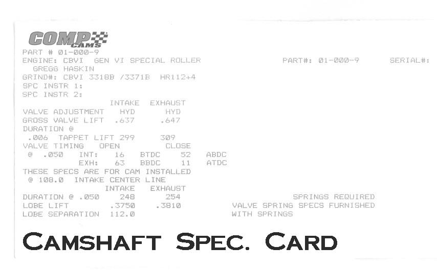
My Competition
Cams hydraulic roller camshaft CAM CARD is now loaded onto the website.
January 28th & 29th,
2006:
Bright &
early on Saturday morning, Kurt and I began the work necessary to stab in the
completed 540” Big Block Chevy engine and transmission. I used the lift gate of the shop truck as a
work platform to install the flywheel, block-saver plate, clutch & disc, bellhousing and clutch fork. We picked the engine and using the tilting
device, dropped it down onto the mounts.
Prior to dropping in the engine, we laid the headers down along the side
of the frame and held them in place with bungy
cords. A blanket was used to protect the
firewall from any contact.
We then
raised the car on the lift and tried to install the
Sunday was
spent working on clutch rod installation and some engine parts like the Holley
Commander 1,000CFM throttle body, air cleaner, spark plugs, thermostat housing,
Moroso valve cover gaskets and adjusting the toe-in
to a closer setting than it was. Exhaust
system install is next, but after a order from Jeg’s for a larger pair of header collectors (with an O2
sensor port) and some S-bend tubing to get better alignment with my trans crossmember.
February 11, 2006:
The stainless
steel fuel tank from Rock Valley Antique Auto Parts was installed today. Prior to installing the tank, the sending
unit bracket had to be cut to the appropriate length based on the tank
depth. A float rod also had to be cut,
bent and installed into the resistor of the sending unit. I chose to run a –8AN feed line and a –6AN
return line to and from the tank. I made
up the tank end of the fuel lines, connected them and raised the tank into
position. Stainless steel straps were
provided with the tank and after centering it between the frame
it was bolted down. I made up a generous
length of wiring for two grounds, a sending unit lead and a positive fuel pump
lead, all taped together in a bundle for wiring later. Fuel lines were next, but I quickly
discovered that the Mallory canister-style fuel filter was not going to work on
the car. With limited mounting choices,
it would have hung down below the frame and been an eyesore. I chose to order an Aeromotive
in-line style fuel filter and billet aluminum mounting bracket from
February 13, 2006:
I mocked up
the Vintage Air FrontRunner serpentine drive kit
today. This accessory drive system is nothing
less than brilliant! It allows me to
mount the A/C compressor, power steering pump, reverse-rotation
water pump and 140Amp alternator using a single serpentine belt. Photos are loaded on the Engine & Drivetrain section of this site. Enjoy!
Next weekend I will focus on completing the fuel lines & filter
installation, then start the exhaust work.
February 18-20, 2006:
Making the
most of the 3-day weekend, I dove in on Saturday morning to complete the
routing of the fuel lines and placement of an in-line fuel filter from Aeromotive Industries.
This fuel filter is a very nice billet aluminum piece, and I ordered the
mounting bracket too. The filter is now
mounted to the frame brace that connects the upper and lower frame rail at
about the mid-point of the door.
Continuing the fuel line routing, I ran the feed & return lines thru
the frame where the stock line would have been routed. It was a tight fit, but the lines made it
thru the small openings. The lines now
become visible for the first time at the frame hole near the passenger side
motor mount.
The Flowmaster 3” exhaust system was nothing short of a pain in
the ass to install. Because I was using
an aftermarket transmission crossmember, the H-pipe
width at the front of the exhaust was not going to line up with the width of
the crossmember openings. In short, I had to modify the H-pipe by
decreasing its length. After doing that,
the connector pipes were fit and welded into place onto the H-pipe and
collectors. The tail pipes are still in
need of some minor adjustment so they don’t make contact with the fuel tank and
frame, but I can do that later.
On Monday, I
began the installation of the steering column and connector shaft. A new firewall sponge seal was also
installed. Brake booster rod was
connected and the clutch connection rod will be fabricated using small steel
tubing and spherical rod ends. One note
concerning the steering column, I had a company in New York make me a custom
column incorporating the following features:
1. Direct fit into the ’71
Chevelle with no modifications needed; 2.
Dimmer switch located on the directional wand; 3. Wiper controls located on the directional
wand; 4. Cruise Control located on the
directional wand. The cruise feature
will be added at some time in the future after the car is completed. Pictures of the fuel tank and exhaust system
are located on the new page “Fuel, Electrical & Exhaust”.
February 22, 2006:
Yesterday I
received a weld-in bung and billet aluminum oil fill cap for the valve
cover. After drilling a 1.5” hole with a
holesaw, I had one of our supervisors Scott Ross drop
off the valve cover at an area equipment repair and steel shop. Bobby, one of the owners, tig
welded the bung onto the valve cover from the backside, leaving the exterior of
the bung with a nice, clean look. Now
the opposite side valve cover needs a hole drilled to allow me to use a K&N
push-in breather.
February 25 & 26, 2006:
This weekend
I concentrated on making my MSD 8.5MM super conductor spark plug wires. Starting at the spark plug end, I routed the
wires thru the GM seperator looms, and cut them to
length at the distributor cap. Using my
new MSD crimping tool, adding the boot at the distributor end of the wires was
a snap. Then I mounted the MSD Blaster
SS coil onto the firewall and made up a short connector wire to the
distributor.
Next, I
installed the fuel injectors onto the fuel rails. I then added the Russell Endura
hose ends to the stainless steel braided lines and connected them to the feed
& return ports on the fuel rails.
I’ve ordered a pair of hose separators to keep the fuel lines together
instead of using zipties. Next weeked I will
start working on plumbing the hydra-boost brakes and power steering box.
March 11th & 12th,
2006:
Over the two
days this weekend I completed the following items on the Chevelle: Installation of the hydroboost
brake system braided steel lines & fittings, Lokar
throttle cable and stock gas pedal, powder coated clutch pushrod, main brake
lines from master cylinder to distribution block, Earl’s polished aluminum hose
separators on the feed & return fuel lines, plugged the extra O2 sensor
port in the driver-side header collector, fuel tank vent line and K&N
mini-filter and parking brake tension line and retainer clips. I also installed the Holley fuel injector
wiring harness. The Ron Davis radiator
is here, but will not be installed till the radiator support is sent off for
painting.
April & May, 2006:
With parts at
the paint shop and no deadline in sight, I suppose getting this car to
Chevelle-abration 2006 in
The Vintage
Air A/C & heater unit is installed using a custom bracket I built. I’ve started the duct work, and need to make
up the four short hoses on the drivers-side of the firewall. Wiring is simply plug & play, with
pre-installed terminals that plug into the control panel mounted to the
dash.
I have chosen
to use Covan Classic’s ABS brushed aluminum dash
insert, with Autometer Ultra-Lite
series gauges. It has all arrived and
will need to be installed and wired during the wiring phase.
Sound
deadening material is being added to the firewall and floor of the car, with
more planned for the insides of the doors, roof, trunk divider panel and
wherever else I can think of. I purchased from a company in
June & July, 2006:
I took a
break to attend my 4th consecutive trip to
Anyway, back
to the resto!
I’ve been working thru the issues of cutting, crimping fittings and
routing A/C lines and heater hoses.
Working in tight quarters up under the dash for the line connections is
a royal pain in the arse, but I have them completed
finally. Actually, o-ring and final
tightening is still needed, but now I can focus on other things. The biggest “other thing” right now is to
begin wiring the car. I’ll start with
the pre-assembled Holley MPFI wiring harnesses and then start the
infrastructure for the rest of the car.
I would like to fire the engine in a month’s time, give or take. While that sounds like an easy task, and it
would be with a standard carburetor-equipped car, it’s not quite that simple in
this vehicle due to the MPFI, in-tank fuel pump, A/C system, electric fans,
etc… I have to wire the car for the
basics before thinking of trying a start of the engine. Stay tuned….more to come!
July 8, 2006:
With all the
best intentions, I set out to begin the installation of my wiring. The Holley Commander 950 kit includes its own
separate harness which connects the ECU to all the engine sensors, plus a few
external needs like 12V hot, 12V switched, ground, etc… I mounted the ECU on top of the glove box,
and it will be accessible (although not necessary) by removing the dash
pad. A hole was drilled in the top of
the glove box and the data port lead hangs down thru the hole. PC can be hooked up simply by opening the
glove box and connecting the cable. The
harness was routed thru the firewall using the speedometer hole (slightly below
the gas pedal) and all sensors were hooked up.
The only remaining sensor to be hooked up is the oxygen sensor and
cable, which will be completed when the control unit for the sensor is located somewhere, TBD.
I then
unboxed the American Autowire Highway 22 wiring kit,
and tried to locate a good spot for the fuse panel. Unfortunately, the fuse panel is much larger
than an original one, and I cannot find a good location for it. I do not want to install it under a seat, or
in the trunk, therefore I’ve chosen to use original style harnesses for the
car. I placed an order with NPD for all
the car’s wiring harnesses. The goal is
to be able to start the Chevelle in August!
February 6, 2007:
AUGUST? Yeah, right!
The project
kind of hit a wall, or at least my interest level did, throughout the fall of
2006. I decided to move the Chevelle
from my business to the workshop at my parents house,
just about a ½ mile away. After cleaning
out the shop to make room, it was moved and will be in a much better location
for the remaining work. Just as the NFL
season was winding down, I began working really hard on the car.
Recently, I
have done a lot of wiring work. For
example, the dual SPAL fans on the Ron Davis Radiator have been wired using
separate 30amp relays. I’ve installed
the American Autowire stock harnesses into the dash,
and engine compartment. New battery
cables, horn relay, horns and battery junction block have all been
installed. Next, I wired a relay in the
back of the car to power the electric fuel pump. I’m running a heavy gauge wire from the
battery along the frame fuel lines, to the relay. The relay is triggered by a wire coming out
of the Holley Commander 950 harness, routed along the inside floor where the
intermediate lighting harness goes.
I am probably
within a day’s work from being able to fire up the engine. A few wires from the Holley Commander 950
harness (12V, IGN 12V, Ground, Wide Band O2 sensor & control box) need to
be installed and I should be ready.
February 9-10, 2007:
The last of the small issues were resolved on Friday afternoon,
and it looks like Saturday the 10th will be the first attempt at
starting the engine! I had to order a
strait piece of flexible radiator hose for the lower position, turns out a
stock lower hose isn’t large enough to slide over the Stewart reverse-rotation
water pump that was included in the package from Vintage Air. Parts store quickly came thru with a 2”x18”
hose and I installed it on Friday.
On Saturday morning I stopped off at the local supermarket to buy
three gallons of distilled water, for making a 50/50 mix of anti-freeze. After making a four gallon batch, I added it
to the radiator. I hooked up the coil
and hit the key.
The motor sputtered, as if the distributor was out of adjustment. I fought for quite a while with the
distributor, even removing the cap and rotating the engine over to TDC on the
compression stroke….all was OK. I like
to install my distributors so that when the #1 cylinder is at TDC, the rotor
points directly towards that cylinder.
Nothing was wrong here, so I had to figure out some other solution.
Digging into the Holley tuning guide, it turns out that the reason
the engine wouldn’t start was that the ECU had too lean of a fuel enrichment
setting during cranking. I accessed the
fuel map, made a 2 millisecond increase to the enrichment setting for a cold
motor, and lo & behold…..the engine fired right up. Within about 15 seconds I had to shut her
down though, because my heater hoses leading into the fire wall were leaking
water like crazy. I removed and looped
one of the hoses temporarily between the pump and the intake. The hydro boost master cylinder was also
leaking power steering fluid…that issue can be resolved by slightly relieving
the area where the AN fitting is hitting it, not letting the crush washer take
full torque. I got that leak slowed down
enough to start the motor again.
I kept the idle a bit over normal to help bring it up to operating
temps. Since this is a hydraulic roller
cam, there was no need to do the “cam break in” deal…..but I wanted to perform
several warm-ups and cool-downs to seat the rings. Oil pressure was rock solid, at 45 PSI at
idle, about 60 with higher RPM’s. When the temperature reached 195-degrees, the
dual SPAL fans kicked on. For some
reason (I still am not sure why…) one of the fans stopped turning. After I shut down the engine I checked the
fuse and found it blown. I replaced it
and it hasn’t happened again.
Anyway, it’s been a long time coming…and I’m very pleased the
engine started and ran great for now.
With the HAYS aluminum flywheel I installed, the engine spools up in RPM’s very, very quickly.
This car should be an absolute BEAST to drive…I can’t wait! A lot of additional tuning is necessary to
make the engine work at peak performance.
I read a bunch of the Holley manual this morning and was surprised at
how much more there is to do. It’ll be
worth it though! Bleeding of brake
system next, then I want to see if the car moves under
its own power. Stay tuned and thanks for
checking in.
August 20, 2007:
Well, there’s a lot to get you caught up on…some information will
be disappointing, but encouraging to others (including me)! Let me start by going back to early spring
shortly after getting the 540 fired up with the Holley fuel injection. If you read the Feb. 9-10, 2007 blog above,
you’ll be led to believe that the engine just needed a bit more tuning and all
would be well. I found that the tune
went away, and even after input from Holley tech and others, I couldn’t get
back to a point where the engine would behave.
The fuel curve was so rich it actually fouled the oil. I caught it in time (very thin oil = low, low
oil pressure) and re-grouped. It came to
the point after Chevelle-abration (June) that I chose
to make a drastic decision. Against the
advice of some of my friends on Team Chevelle, and with the support of others,
I removed the fuel injection system in favor of a regular intake & carburetor. At least this way I would most likely be
driving the car sometime this year vs. next year…maybe.
So, after all the parts arrived (Edelbrock RPM Air-Gap intake, BG
850VS Carburetor, MSD Ready-to-run distributor, Mallory fuel regulator) I dug
in. It was at this point where I
discovered a near-fatal assembly error on the engine. While completing final assembly of the valvetrain items back in January 2007, I somehow got
distracted and installed the Comp Cams hydraulic roller lifters BACKWARDS !!!! I
noticed this during the intake manifold swap, and was absolutely outraged at my
stupidity. A close inspection with a
flashlight revealed the cam lobes were gouged and the lifter wheels were
scuffed too.
After re-gaining my composure, I made calls to have Comp Cams
re-grind my custom bumpstick, still in their computer
database, along with a new set of roller lifters. The engine was yanked out in early July for a
partial tear-down. Minute metal debris
was found in the filter, but no where else in the engine. After replacing the cam with the newly ground
piece, the engine was re-assembled. We
re-installed into the car on July 28th. One silver lining, if you can call it that,
is the opportunity to install a high-volume oil pump in place of the first one,
a stock replacement pump. During the initial
star-up phase I wasn’t happy with the amount of oil pressure, and the new HV
unit solved that. Now the pump will
match the one in my ZZ502 motor in my ’72 Chevelle SS car.
After another two weekends of final installation items like fuel
line mods, regulator install, MSD
distributor swap, it was time to fire up the old girl. Prior to fire-up, I let the fuel pump prime
and discovered that there was way too much pressure at the carburetor, even
after knocking down the incoming fuel at the regulator. Seems that my return line to the tank (-6AN)
is too small, so some -8AN line and fittings were ordered. The line was replaced on August 18th
and the engine was fired up once more.
It sounds extremely NASTY, with the Flowmaster
3” exhaust and turn-downs just after the mufflers bouncing off the
concrete.
The milestone of the next day was over four and a half years in
the making: I ACTUALLY DROVE THE CAR
around my business’s parking lot today (Aug. 19th) for a feel of how
the parts work together. The car is
still a bit twitchy, sensitive to power, brake pedal is still a bit hard, it
needs to be timed & tuned, but this is a great start. Now I can finally install the front clip sheetmetal. I would
guess that interior over the winter and the car will be road-ready in the
spring.
June 27, 2008:
Why the long gap in updates?
Well, it seems that the excessive fuel pressure damaged the Demon carb, and the engine began running so poorly and became so hard
to start that I got frustrated (again…) to the point that I just stopped
working on the project. Plus, I had my
new workshop built over the winter. In
the spring of 2008, I moved all my projects & cars to the new shop and
began working on the Pro Touring car again.
A friend suggested that I remove the perfectly running Demon carb off my ’72 Chevelle SS 502-equipped car, install it
onto the Pro Touring 540 and see if it would run good. Lo & behold….it did the trick, verifying
that the other Demon had been damaged by the excessive fuel pressure. It turned out that the in-tank fuel pump that
I had originally installed for use with the Holley MPFI fuel injection kit was
too high a volume, and the bypass fuel pressure
regulator just couldn’t keep up with the flow.
That’s why the pressure couldn’t be dropped down to carburetor-friendly
numbers. I replaced the in-tank pump
with one just slightly smaller. Fuel
pressure can now be dialed in to the 6.5 PSI required for the Demon. Another Demon was ordered (I could have
repaired the other one, but chose to just buy new) and the engine now starts
great, choke is adjusted for no more than a 60-90 second run time before it
kicks off, and the response is phenomenal!
So, last night I transported the car from my new shop to the local
airport where I fly out of. Using some
of the long taxi-ways, I was able to drive up thru the gears, getting a feeling
for the car. This has now given me the
ambition to get busy on the project again.
Updates to come again!
June
30th, 2008:
Wow! Another update only three days later!
Taking
advantage of the weekend, I did some more “testing” of the Chevelle at the
airport. Mostly going up thru 1st
and 2nd gear, I wanted to confirm that the car started consistently,
idled consistently, heat-cycled like normal and maintained solid oil
pressure. Everything seemed fine,
although I need to put a timing light on the engine
and adjust the advance. One of the
disadvantages of running a manual transmission car, with an aggressive camshaft
and certain rear-end ratios, is that at low speed driving (such as parking
lots, driveways, etc…) the car may have the tendancy
to “buck”. This is somewhat cured by
reducing the ignition advance timing. I’m
curious to see if it solves my bucking issues.
Some might say that it is normal, and the car needs to be driven with
that symptom in mind, but I would rather do what I can to reduce it.
So, getting a
bit more adventurous, I was able to “get on it” slightly and do
an aggressive 1st to 2nd rip. This car puts my ZZ502-equipped ’72 Chevelle
SS to shame! In the wrong hands, this
car will be DANGEROUS!!!
My friend
Richard stopped by, and I asked him to do some laps back and forth so I could
hear what the car sounds like….Neat tone!
The 3” Flowmaster dual exhaust with Super 40
mufflers and turn-downs make this car, to quote Richard, “sound pissed off”.